Data display in the drivers seat
- gscalfaro
- Sep 23, 2023
- 6 min read
I have a four camera DVR system on the van, that generally I use for a rearview mirror while driving.

I have a Victron Cerbo collecting data from all my critical systems on the van. My goal is to have all that data available while driving.

The good news is that my Victron Cerbo System allows me to capture a lot of data to fill me in on how the various are working, be that temperature of the refrigerator, how full the tanks are, and how well the electrical system is doing, mainly the battery. The 7-inch screen of the Cerbo GX allows instantaneous access to that data. Victron also has a cloud service to keep your data on. The data is easily accessed via your web browser from either phone or laptop.
On my old 2004 Sportsmobile, I use to run a Carputer for infotainment, it had a rearview camera system, and I wrote some custom plugins to capture some data from my electrical devices. I eventually wrote a tablet friendly program to handle all those things. I thought I would dust off that program and rewrite with the abilities of my new system. Luckily for me, the old system talked to my Morningstar Solar controller with a protocol called Modbus. It just so happens that one of the protocols you can use for the Cerbo Gx system is Modbus. This is all over network, so no extra connections are needed.
I needed a platform to run this new program on, I didn’t want to pull out the old carputer, but I found a small MeLE PCG02 Fanless Mini PC Stick Computer.

This has a very small footprint, it currently is attached to TV mount with tie wraps, accessible but out of the way. The power is provided by a Type C USB cable witch is plugged into a USB charging Port. To get the video into the computer, I originally had a cheaper older device that I found was giving me video issues. I now use a ClearClick Video to USB-C 1080P S-Audio Capture device.

The video input also goes directly to the monitor, providing a backup path. This plugs into one of the two USB 3.0 Inputs on the computer stick. The second USB input is used by my touchscreen monitor.
This is the main page of the program. This page has date and time status in the upper right corner. The green antenna on the camper indicates it is connected, red would be disconnected. The remainder are buttons for the subsequent pages.

The one that we are really looking at for this post is the rearview mirror, where we combine the Camera System and Data collection. The focus of the page is camera view, but we wanted to provide data that was pertinent to the driver. The most important data is on the left-hand side of the screen, this allows us to see pertinent battery data Voltage, SOC, Current, Temp and Amp-Hrs. The remaining spots are for the alternator current, and alternator temp. This is important, do to running a second alternator with a Wakespeed controller. The alternator can be turned on with a switch on the overhead console.
On the top row, we again have an indicator of network connection, Altitude, Heading and # of Sat's. This data is all connected via the Victron systems connected USB. I added the County and State information after driving through Nebraska getting a bunch of Weather alerts, which were by county. Unfortunately, I had no idea what county I was in. I get the State and County information via an API on a government census site. You provide the latitude and longitude, and it provides the data output.
The bottom row has previous and next buttons, along with the start camera button along with the starter battery voltage, main page button, refrigerator temperature and finally the fresh, gray and propane tanks. We also have a button called temp that will bring up temperatures on the left panel. From the driver’s seat I have a lot of data that I can scan to know what the status of my systems are.

While this was the focus of writing the program, I decided to fill it out with more data with each panel focusing on different devices. The first on collects data on my battery system. My Lithionics battery has a external BMS that communicates with the Victron Cerbo. That enables me to pull that information from the Lithionics battery. I also have a Victron Smart shunt hooked up, this let’s me compare the two, but also the Smart shunt has better historical data. I also get the starter battery voltage via the Smart shunt.

The next screen will be for the Victron Smart Solar Charger MPPT 150/60. This screen will allow me to capture data relevant to the performance of the solar system. The upper left has all the data for the panel performance below that we will have some data on the yield and max power for both today and the previous day. On the upper right of the screen, we show data pertaining to the output, such as Volts, Current, Watts, and efficiency of the system. Below we have the output of the solar Irradiance meter. I keep track of the max value and average it for the day and the cell temp. I round out the screen with some battery data, so I don’t have to flip back.

The next screen is pretty much a collection of data from all the components connected to my Victron Cerbo Gx. On the right-hand side, I display temperatures collected via various sensors, most of those are connected via Bluetooth and are made by Ruuvi, I also display some that are direct from other sources such as the battery and solar irradiance meter. All these sensors capture the min and max temperatures, which can be asked with a button on the bottom. Below that we find some GPS data. In the middle we again have some battery data followed by some individual load data. I currently directly measure the refrigerator power usage, in Whs and AHrs, and the percentage of time the unit is running. We also collect data for the two Maxx Fans on the roof. And finally, every other dc load is wrapped together. The left-hand side displays data for the three tanks, fresh water, gray water, and propane.

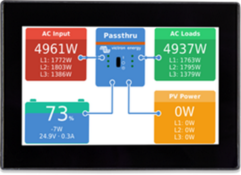
The next screen is devoted to the Victron MultiPlus-II 12/3000/120-50 inverter/charger. It provide key information, such as shore power input, voltage, current, watts and frequency. You can also see on the AC load side the same data and the battery and current which is important in inverter mode. The VE Bus state can be seen, in this case you can see that it in passthrough mode. Below you can see the main switch functions, Charger Only, Inverter Only, On, and Off. To the right you will see to buttons for Charger Relay and MPPT relay. These relays are on the Cerbo, but I use them to turn on the charger and Solar. The main reason for the charger relay is to keep the unit in Passthru without charging the battery. This is done by setting the charge rate to zero (off) as default. When the relay is enabled the charge rate is increased to the desired amount. Victron also has a current limit setting, while this can indirectly change your charge rate, in it is limiting the incoming power. It is a nice feature to use when switching from a 15-amp input to a 30-amp input. The unit supports 50 amps by I am only wired for 30 amps.

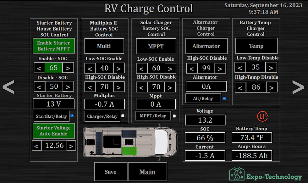
The next screen screen is devoted to Charge Control or the automation of charge control.

While the investment in Lithium batteries has been great, I would like to protect that investment as much as possible. There are two key pieces of data that I have access to battery SOC & battery Temperature. While I don’t have a problem charging my battery up fully when going on a trip, for those times when it is stored, I don’t want it at 100% SOC all the time. I put controls on enabling the chargers based on SOC. If the SOC drops below one set value the Multiplus will be turned on, if it gets above a set value it will turn it off. There is also a separate control for the solar controller.

All chargers can be shut down when outside of the set temperature values. I have a low temp setting and high temp setting. This is mainly used as a high temperature control.

My alternator is usually my most powerful charger (140+ Amps), and as a secondary safety measure I added the Alt/Charger control. This allows me to disable the Wakepeed alternator charger, at a particular SOC value, I usually have this set to 99 or 100 %. I have found that the Wakespeed profile for my battery is actually very good, so this feature may not be used much.

The last option is for the start battery. It will essentially switch one of my PV panels over to my solar controller for my starting battery. This is based off of SOC level of the main battery, but there is an auto engage setting based on starting battery voltage.

The next page is for manuals, this page links you to different digital copies of manuals for much of the equipment used in the van.

There are couple of work in progress pages such as the system check page, This is just another way to display some of the key data. I expect there will always be some changes in the works

While this program was primarily designed for display of data while driving, I also use it on my home PC and Laptop in the van.


Comments